
Split-Core Residual Current Transformer Supplier for Reliable Leakage Current Monitoring
2026-09-08
Every maintenance team has faced it: a residual current reading that flickers just above the alarm threshold, but no one wants to shut down the line to diagnose it. Split-core residual current transformers solve that dilemma by clamping around live conductors, so you get continuous leakage current data without a costly outage. The catch? A split-core RCT is only as reliable as its supplier's manufacturing consistency and calibration. Xiasen focuses on exactly that—producing split-core RCTs that maintain their precision after installation, in the real mess of a distribution panel. Read on to see what separates dependable leakage monitoring from guesswork.
Leakage Monitoring That Fits Around Live Conductors
Traditional leakage current monitoring often forces you to shut down equipment, disconnect cables, and thread bulky CTs over conductors. That approach works in a lab, but on a live production floor it means downtime nobody can afford. Leakage monitoring that fits around live conductors removes that barrier entirely—the sensor clamps or hinges open, slips over the insulation, and locks in place without interrupting service. No rewiring, no scheduled outage, no risk of arc flash from an accidental disconnect.
The trick is in the split-core or flexible Rogowski design. Instead of a solid toroid that must be threaded from the end, these monitors use a hinged magnetic path that closes around the conductor. Some models even use a thin, flexible coil you wrap and secure with a velcro strap—works on odd-shaped busbars, large feeders, or tightly packed cable trays. Accuracy holds up because the core geometry is compensated for the air gap at the joint, and the signal conditioning filters out nearby electromagnetic noise. You get a true RMS leakage reading without pretending the conductor is perfectly centered.
In practice, this means a facility electrician can walk up to a running motor control center, snap a monitor around each phase conductor, and start logging leakage trends within minutes. Older buildings with aging insulation benefit most—you can spot gradual degradation before it trips a GFCI or causes a fire. Data centers use the same approach to monitor UPS output feeders without ever taking a rack offline. The real difference shows during retrofits: instead of planning a weekend shutdown for sensor installation, you do it during normal operation, and the monitoring system starts paying back the same day.
Why Split-Core Design Changes Maintenance Workflows
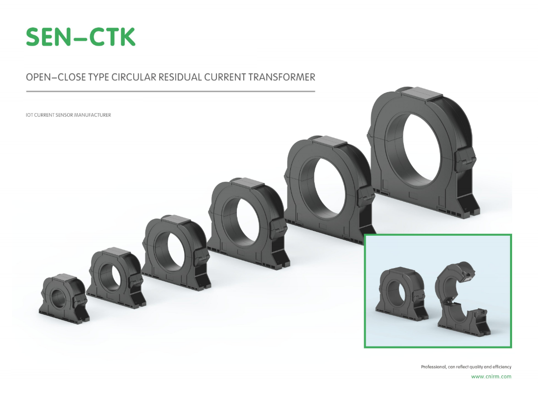
Maintenance teams used to schedule shutdowns just to get a current reading. With split-core sensors, the job flips: clamp the core around an existing conductor, secure the latch, and walk away with live data while the system keeps running. That single change removes the most tedious part of panel retrofits—no cable disconnection, no re-termination, no risk of introducing a new fault during reassembly.
The practical impact shows up in how work orders are written. Instead of bundling electrical metering with planned outages or weekend overtime, technicians can handle installation during a routine walkthrough. The hinged design also means one person can complete the job in tight enclosures where pulling conductors would require two sets of hands. Recalibration and replacement become just as straightforward: unclip the old unit, clip on the new one, verify the output.
Over time that shifts maintenance from reactive to opportunistic. Teams stop deferring energy audits because the cost of entry is no longer a full shutdown. Facilities can add monitoring points incrementally, on the same day a problem is suspected, without waiting for the next maintenance window. Split-core design doesn't just change how sensors are installed—it removes the operational penalty that used to justify leaving blind spots in the system.
Choosing the Right Residual Current Range for Your Site
Getting the residual current range right isn't about picking the highest number you can find. It's about matching the protection level to what your site actually needs—too low and you'll deal with endless nuisance trips, too high and you might as well not have the breaker at all. Start by looking at the equipment you're running and the environment it lives in. Outdoor sites with moisture or portable tools typically call for tighter thresholds, while fixed installations with steady loads can often handle a more relaxed setting.
A common mistake is treating the residual current rating as a one-size-fits-all figure. Different circuits serve different purposes: a lighting circuit doesn't need the same sensitivity as a circuit feeding hand-held power tools. Map out your distribution board and assign ranges based on actual risk rather than convenience. For example, circuits supplying socket outlets in wet areas or construction zones usually justify a lower trip current, whereas dedicated circuits for large, stationary machinery might work fine with a higher residual range if the risk of direct contact is minimal.
After installation, don't just walk away and assume the chosen range will hold up forever. Seasonal changes, added equipment, or even minor wiring alterations can shift the leakage currents on a site. Periodically test the residual current devices under load and listen to what your team reports—if breakers trip too often or not at all during a fault simulation, it's time to revisit those settings. The goal is a range that protects people without stopping work every time a bit of dust or humidity sneaks in.
Installation Practices That Keep Readings Stable
Stability starts long before you take the first reading. One of the most overlooked mistakes is mounting a sensor to a surface that flexes with temperature changes. A thin metal bracket might seem rigid on the bench, but as the enclosure heats and cools, it moves enough to shift the zero point by a few microstrains. Use a thick, isolated base plate or a ceramic standoff, and keep the sensor away from fans, exhaust vents, and direct sunlight. Even air currents across a bare sensing element can create slow drift that looks like a real signal.
Cable routing matters just as much as the mount. When a cable is pulled tight between a fixed conduit and a moving structure, it can act like a spring, tugging on the connector and changing contact resistance. Leave a service loop, and anchor the cable at two points with a soft clamp in between. For high-sensitivity measurements, route signal lines away from AC power and use twisted shielded pairs with the drain wire tied only at one end. Ground loops are a common source of wandering baselines, so avoid connecting the shield at both the sensor and the logger unless the manual explicitly tells you to.
Supply Consistency for Multi-Site Retrofit Projects
On a multi-site retrofit, inconsistent supply turns up fast. One building gets lighting fixtures with a different driver model than the next, and the crew loses half a day adapting brackets and wiring. Or a promised delivery for a specific air handler slips, leaving three sites half-finished while the team jumps to a different location. Consistency here is less about ordering everything upfront and more about locking exact part numbers, vendor lead times, and drop-ship schedules before the first site is touched.
Central procurement helps, but it has to connect to a realistic phasing plan. Instead of treating all locations as one giant order, split the rollout into waves. For each wave, confirm that the same version of every component—lighting controls, panels, trim, fasteners—is available in the quantities needed. If a product is being discontinued or has regional stock gaps, revise the specification before it becomes a field issue. Reworking a drawing is far cheaper than reordering materials after installation has started.
Substitutions are another risk across multiple sites. A supplier may offer an "equivalent" item that looks fine on paper but creates maintenance headaches later. Keep a short list of approved alternates, and require a written sign-off for any deviation. That way, future service calls don't turn into a search for parts that don't match the original install.
Signs Your Current Transformer Is Undersized for Leakage Currents
One of the first things you might notice is that the readings simply don't make sense. A CT rated for hundreds of amps will produce only a whisper of secondary current when asked to measure a few milliamps of leakage. The result is a signal that sits close to the noise floor, jumping around or stubbornly clinging to zero despite known fault conditions. This isn't a calibration issue—it's a fundamental mismatch between the primary current range and the CT's design window.
Another telltale sign appears during transient events. Leakage currents often spike briefly during motor starts, insulation stress, or ground faults. An undersized CT can be pushed into magnetic saturation during these short bursts, causing the output waveform to flatten or distort. Protection relays may then trip late, fail to trip, or chatter unpredictably. If you've ever watched a relay behave erratically only during certain load conditions, the CT's core may be gasping for magnetic headroom.
Finally, keep an eye on temperature. While leakage currents are usually small, an undersized CT can still run warmer than expected if it's forced to handle harmonic-rich or spiky waveforms. Extra core losses from high flux density show up as a slightly hot casing or a faint hum that wasn't there before. It's easy to dismiss, but combined with odd readings and occasional saturation, it points squarely at a CT that's too small for the job.
FAQ
Focus on the core material and the hinge design. A high-permeability core with a smooth, tightly closed split keeps phase error low, while a robust hinge ensures consistent performance after repeated clamp-on installations. Also check the shield layer between primary and secondary—this cuts down interference from adjacent conductors.
Yes, that is the main reason to choose split-core. You open the core, place it around the conductor, and close it without interrupting service. Just make sure the mating surfaces are clean and the locking mechanism is fully engaged; any small gap can degrade accuracy.
Common outputs are 1A or 5A for older electromechanical relays, but many modern monitoring systems prefer millivolt or milliamp signals. You will also find units with built-in burden resistors that give a voltage output directly proportional to the residual current.
Measure the largest conductor diameter you need to clamp around, including insulation. The transformer aperture should exceed that by at least 10–15%. For bundled cables or multiple parallel conductors, treat the bundle as a single conductor and pick an aperture that fits the whole group without forcing.
Solid-core transformers can achieve slightly better accuracy because there is no air gap, but a well-built split-core with precision-machined mating surfaces and a strong clasp can come very close. The reliability advantage in retrofit and temporary monitoring scenarios outweighs the small difference, because you can install it correctly without shutdowns or rewiring.
Incorrect conductor placement, especially if the neutral or ground conductor is not included, is the main culprit. Nearby high-current cables can also induce noise if the transformer lacks proper shielding. Finally, a loose hinge or foreign material on the core faces creates an air gap that shifts the measurement.
It depends on the transformer. Some split-core residual current transformers are sold with an integrated burden resistor and provide a low-voltage output directly. Others require you to connect an external burden matched to the secondary rating to avoid saturation and protect the measuring device.
Keep the transformer away from strong magnetic fields like large motors or busbars with high switching currents. Secure the cable so it passes straight through the center without touching the inner walls. If vibration is present, check the latch periodically and re-tighten if needed. Also record baseline readings after installation so later deviations are easier to spot.
Conclusion
Reliable residual current monitoring often starts with a transformer that can be installed without shutting down the circuit. A split-core design allows the sensing element to open and clamp around existing live conductors, which means leakage detection can be added to distribution boards, motor control centers, or branch feeders while they remain energized. This changes maintenance workflows significantly: instead of scheduling outages or disconnecting wiring, technicians can fit the sensor, close the core, and verify the output in minutes. For sites with continuous processes or critical loads, this is a practical advantage. Choosing the correct residual current range is equally important. A sensor rated for 5A residual current may not resolve a 30mA leakage event that indicates insulation breakdown. Suppliers should help match the range to the fault current you need to detect, whether that is personnel protection at low levels or equipment protection at higher thresholds.
Stable readings depend on installation details. The split-core halves must meet cleanly without debris or misalignment, and the conductor should be centered in the window to avoid positional errors. Cables should not press against the core, and nearby high-current phases can affect accuracy if the sensor is not shielded or properly positioned. For multi-site retrofit projects, supply consistency matters: the same transformer model, mounting dimensions, and output characteristics across hundreds of panels reduce commissioning time and spare parts complexity. A supplier that maintains consistent stock and documented performance curves lets teams standardize wiring and settings. Finally, watch for signs the transformer is undersized for leakage currents. If residual readings saturate at low values, trip thresholds become unreliable, or the sensor output does not change when known test leakage is injected, the core may be too small or the current range too high. Replacing with a correctly sized split-core unit often restores the sensitivity needed for dependable monitoring.
Contact Us
Contact Person: Liu Mengyang
Email: [email protected]
Tel/WhatsApp: 8618727589233
Website: https://www.cnlrm.com/en/