
SF6 Load Break Switch Factory Guide for Reliable Power Distribution
2026-08-27
A load break switch rarely gets attention until it fails—then it becomes the most expensive component in your network. This factory guide pulls back the curtain on SF6 load break switch production, showing where reliable power distribution is actually won or lost. If you’ve ever wondered why some switches last decades while others degrade early, the answers are usually hidden in plain sight on the factory floor. That’s also where Deepwill enters the story.
The Hidden Role of SF6 Gas Purity in Switching Performance
SF6 purity is rarely the first parameter checked when a circuit breaker starts showing inconsistent interruption, yet it sits at the center of arc quenching behavior. Even small amounts of moisture, air, or carbon tetrafluoride shift the gas mixture's thermal conductivity and electron attachment rates enough to weaken the dielectric recovery window after current zero. A breaker that passes routine insulation resistance tests can still restrike under fault conditions because the contaminated gas fails to re-establish insulation quickly enough.
Impurities also accelerate the formation of corrosive decomposition byproducts. Traces of oxygen or water vapor react with sulfur and fluorine fragments during high-energy arcing, producing compounds such as SOF2, SO2, and HF. These species attack contact surfaces, nozzle materials, and sealing elements, gradually increasing contact resistance and slowing mechanical operation. Over time, this hidden chemical wear changes interruption timing in ways that no standard timing test will reveal until a critical switching operation fails.
Maintaining gas purity above 99.9% and keeping moisture within tight dew point limits does more than satisfy a specification sheet. It directly stabilizes arc cooling, shortens arcing duration, and reduces contact erosion. The hidden role of purity becomes obvious only when switching performance is compared under identical electrical stress but slightly different gas conditions: the purer fill consistently delivers faster recovery and fewer restrikes, even though both fills pass the same dielectric withstand test.
How Smart Factories Test Load Break Switches Under Real Fault Conditions
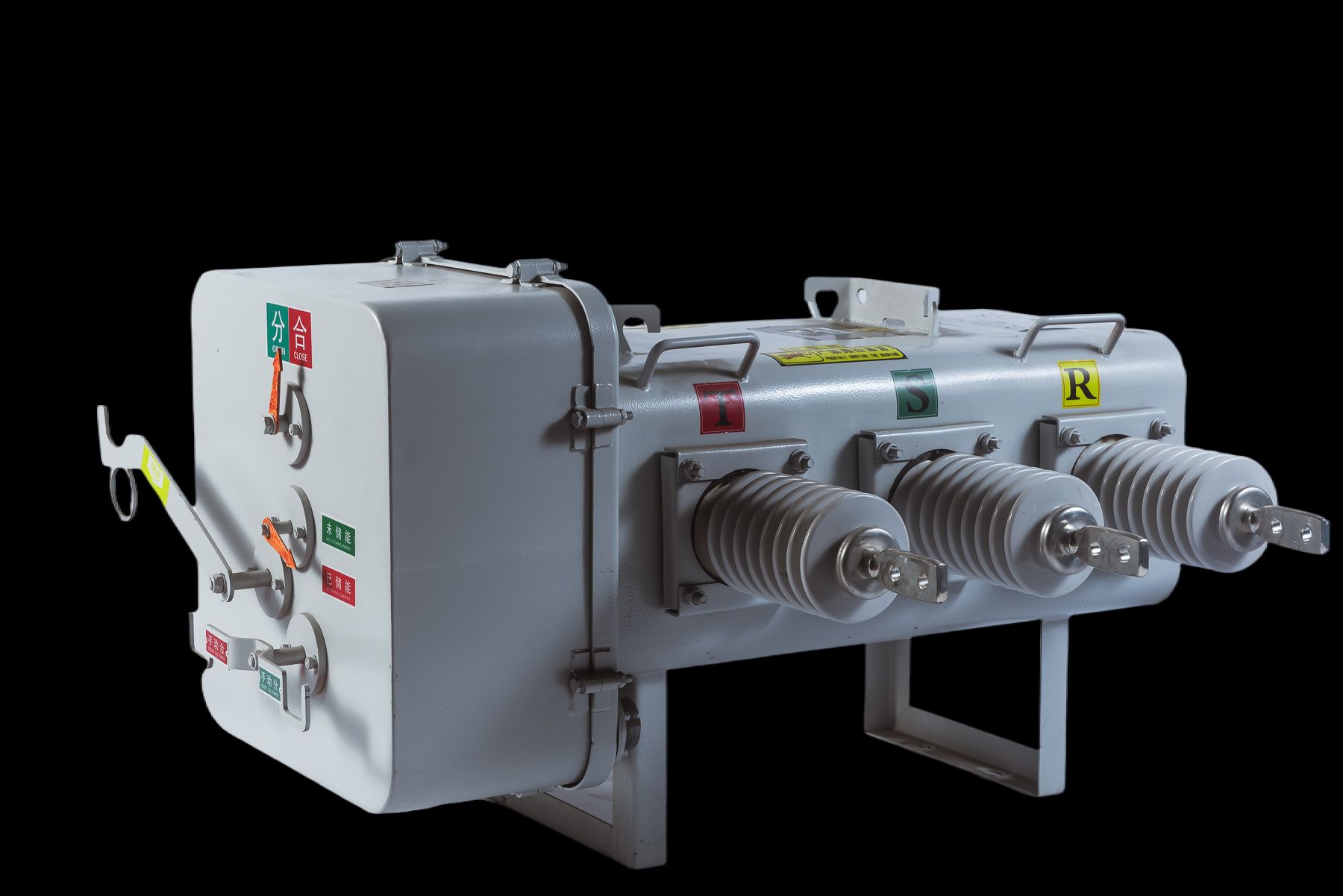
A modern smart factory doesn’t test load break switches by simply opening and closing them under a fixed laboratory current. Instead, the test cell is fed with real disturbance records pulled from utility fault recorders. These digitized waveforms—complete with DC offset, asymmetric peaks, and harmonic ringing—are replayed through a programmable high-current amplifier. The switch under test sees the same electrical stress it would experience during an actual line-to-ground or line-to-line fault, not an idealized sine wave.
Inside the test enclosure, fiber-optic sensors measure arc light intensity and internal pressure at sampling rates above 10 megasamples per second. Contact travel is tracked with linear encoders, and a real-time controller compares the measured opening speed against a digital twin’s prediction. If the contacts separate 1.8 milliseconds too slowly, the controller automatically boosts the injected current on the next half-cycle to recreate the extra arc energy that delay would cause in service. This closed-loop approach means every test run is unique, shaped by the switch’s own mechanical behavior.
The result is a test protocol that blurs the line between manufacturing and forensic failure analysis. Each switch leaves the line with a full time-stamped log of fault events it survived, including reignitions, voltage zero crossings, and contact wear estimated from voltage drop. Because the digital twin is updated after each test with measured data, the factory can spot batch-level problems—such as a spring supplier’s changed heat treatment—before a single unit reaches a customer’s substation.
From Welding to Sealing, Where Reliability Is Won or Lost
A clean-looking weld bead can hide root porosity, undercut, or incomplete sidewall fusion that no visual check will catch. Those flaws don't fail during first article inspection. They wait for a few thousand thermal cycles, then open up as a crack running straight through the throat of the weld. In production, the difference between a joint that outlasts the machine and one that becomes a field recall often comes down to arc length, travel speed, and how well the fit-up was controlled before the torch ever struck an arc.
Sealing failures are quieter but just as predictable. An O-ring compressed to 20% in its groove on day one may lose half that squeeze after a summer of heat soak because the elastomer took a permanent set. The joint still looks fine from the outside, but under a cold start or a pressure spike, the remaining contact stress drops below what's needed to maintain a seal. Gasketed flanges show the same pattern: bolt preload relaxes as the gasket creeps, and the leak that shows up at 10,000 hours was really decided at hour zero by a material choice that couldn't handle the operating temperature.
Where welding and sealing intersect, the failure modes compound. Heat distortion from a nearby weld can pull a machined seal groove out of flat by a few microns — enough to unseat a lip seal under load. Residual stress left in a heat-affected zone can open a micro-crack directly beneath an O-ring land, creating a leak path that doesn't align with any single weld or seal defect. Reliability at that intersection isn't won by inspecting finished parts alone; it's won by controlling the sequence, the heat input, and the post-weld machining so the seal surface stays where the designer intended it to be.
Matching SF6 Switch Ratings to Your Actual Distribution Load
Most switchgear selection starts with a generic short-circuit rating and thermal ampacity, but actual distribution loads rarely align with nameplate assumptions. For SF6 switches, the continuous current rating should be checked against the true load profile, not just the transformer kVA. A 630A switch might seem adequate for a 500kVA transformer at 11kV (about 26A full load), but if the downstream loads include large motor starts or future expansion, thermal derating and temperature rise inside the enclosure matter more than the breaker's breaking capacity. Oversizing by one standard step often costs less than a retrofit.
Short-circuit ratings are frequently overestimated, leading to unnecessary capital spending; conversely, underestimating peak fault current can leave the switch underrated for the most common fault scenarios. Calculate the actual fault level at the switch location, including cable impedance and upstream transformer contribution, rather than using the infinite bus assumption. SF6 technology handles high fault currents well, but choosing the correct kA rating (e.g., 20kA vs 25kA) based on calculated values prevents both overdesign and unsafe operation. Also verify the peak withstand and short-time withstand ratings, as these can be lower than the breaking capacity and may govern the switch's survivability.
Load nature and switching duty also influence rating selection. Frequent switching of capacitive or inductive loads demands a switch rated for the appropriate electrical endurance class, typically M2 for mechanical and E2 for electrical endurance per IEC 62271-103. A lightly loaded distribution network with occasional maintenance switching can use a lower electrical endurance class without compromising reliability. Finally, consider ambient temperature and altitude: standard ratings assume 40°C and 1000m, so any site deviation requires derating. Matching the actual distribution load involves more than comparing amperes; it's about aligning thermal, mechanical, and fault-duty characteristics to real operating conditions.
Why Maintenance Teams Prefer Factories That Document Every Step
Maintenance teams lean toward factories that write everything down because breakdowns don't start from zero. When a machine stops, a technician can open the log and see which bearing was replaced at the last service, what grease was used, and the torque setting. Without that record, they have to tear the equipment apart just to figure out what's already been tried and failed.
Step-by-step documentation also softens the blow of turnover. When a veteran operator leaves, the hard-won knowledge doesn't leave with them. A new tech can flip through the maintenance history and learn what this specific line has done before, which fixes were temporary, and which ones actually held. That beats chasing people around the shop floor.
Finally, maintenance staff trust a factory that treats documentation as part of the job, not an afterthought for auditors. It respects their time. When every step is recorded, scheduling, spare parts ordering, and preventive work all become more predictable, so the team can focus on the judgment calls that actually require human attention.
Avoiding Field Failures with Better Factory Calibration
Factory calibration often gets treated as a checkbox item, but the gap between a quick pass and a truly robust calibration is where field failures breed. When sensors, actuators, and control loops are tuned only to nominal conditions, they can drift silently once installed in a harsher environment. A better approach is to embed realistic stress scenarios into the calibration sequence—cycling temperature, varying load, and simulating signal noise—so the device learns to stay within tolerance long before it ships.
One seldom-discussed culprit is the cumulative effect of minor offsets across multiple components. Individually, each offset might sit well inside spec, but stacked together they push the system toward a marginal operating point. By introducing cross-channel calibration checks and using statistical process control on the final test data, manufacturers can catch these hidden interactions. This turns calibration from a per-unit pass/fail into a continuous feedback loop that tightens the entire production batch.
The payoff appears months later in the field. Devices that were calibrated with real-world variance in mind show fewer unexplained resets, less measurement drift, and stronger immunity to electrical noise. Field engineers spend less time chasing phantom faults, and warranty costs drop noticeably. In the end, spending an extra few minutes at the factory calibration station is far cheaper than shipping a technician to a remote site—or losing a customer's trust altogether.
FAQ
SF6 gas has excellent dielectric and arc-quenching properties, allowing compact designs with high interrupting capability. They handle switching operations reliably even under harsh conditions, reducing maintenance needs compared to air-insulated alternatives.
Quality-focused manufacturers use automated welding, helium leak testing, and pressure monitoring systems. Each unit is filled under controlled conditions and undergoes multiple seal checks before dispatch, so gas leakage stays well below IEC limits for decades.
They appear in secondary distribution networks, wind and solar farm collection systems, industrial plants, and underground substations. Their compact size and sealed-for-life construction make them suitable where space is tight and reliability is critical.
Look beyond certifications. Check whether the factory performs routine tests on every unit, has in-house capability for gas handling and recovery, and provides clear documentation on materials and assembly. A clean, well-organized production floor often indicates disciplined quality control.
SF6 is a potent greenhouse gas, so responsible factories invest in closed-loop gas recovery, recycling systems, and strict handling procedures. Some also develop alternative insulation technologies, but for now proper containment and end-of-life gas reclamation remain essential.
Because the contacts and arc-quenching chamber are sealed inside a gas-filled enclosure, maintenance intervals are typically 10 to 20 years or even maintenance-free for the switching mechanism. The main tasks involve visual inspection, checking gas pressure indicators, and occasional lubrication of external moving parts.
Every switch should undergo high-voltage withstand tests, contact resistance measurement, mechanical operation tests, and gas leak detection before leaving the factory. This catches assembly defects early and gives utilities confidence that the equipment will perform during fault conditions.
Conclusion
The real performance of an SF6 load break switch is decided long before it reaches a substation. Gas purity is not a checkbox; even small amounts of moisture or air lower the dielectric strength and make arc interruption sluggish. A responsible factory tests every filled chamber with a dew point meter and gas analyzer, rejecting units that fall outside tight limits. Beyond gas quality, smart factories stage actual fault simulations: they close the switch into a known short-circuit, measure the interruption time, and record the arc voltage behavior. These tests expose weaknesses that routine no-load operations never show. Then the mechanical side matters just as much. Weld seams around the tank, the compression of O-rings at bushing flanges, and the final helium leak test all determine whether the SF6 stays inside for two decades. Finally, wisely matching the switch's continuous current and short-time withstand rating to the real distribution load avoids both dangerous overheating and unnecessary oversizing.
Field experience shows that maintenance teams rarely complain about a factory that documents too much. They complain about vague test reports and missing calibration data. When every serial number carries its fill pressure, torque readings, trip coil current, and final timing curve, troubleshooting becomes quick and certain. Better factory calibration also prevents the slow failures that frustrate operators: a mechanism that shifts over time, a pressure switch that triggers false alarms, or a contact gap that drifts out of spec. By adjusting each unit against a traceable reference standard, the factory hands over a switch that behaves the same way on day one and year ten. In the end, reliability is not a property of the switch alone but of the process that built it. A thorough factory guide turns scattered good practices into a repeatable sequence, so every SF6 load break switch leaves the plant ready for the exact network it will serve.
Contact Us
Contact Person: Julion
Email: [email protected]
Tel/WhatsApp: 8617351370631
Website: https://www.deyunelectric.com