
OEM AC EMI Filter Selection Guide for Industrial Power Systems
2026-10-22
Industrial power systems don’t forgive guesswork in EMI filtering. For OEMs, the difference between a smooth compliance pass and a late-stage redesign often comes down to one component selection made early in the design cycle. This guide strips away the noise around AC EMI filter choices—current ratings, insertion loss, leakage current, and real-world installation constraints—so you can match the right filter to your motor drives, inverters, or automation equipment. With insights drawn from field applications, DOREXS helps you avoid the common traps that lead to intermittent failures and returned units.
Reading Between the Datasheet Lines: What Actually Matters in AC EMI Filters
Datasheets for AC EMI filters often highlight impressive insertion loss curves measured in a 50-ohm system, but real-world impedance mismatches can drastically reduce actual attenuation. Filter performance in a switching power supply depends heavily on the source and load impedances seen at the line and converter side. A filter that looks excellent on paper may resonate with the input capacitance of a DC-DC converter, creating peaks in conducted emissions rather than suppressing them.
Component tolerances and parasitic elements also rewrite the story between the lines. Inductor core saturation under high differential-mode current, capacitor ESR and ESL, and the self-resonant frequency of common-mode chokes all shift with temperature and aging. A datasheet may specify attenuation at 25°C, but inside a sealed power adapter running at 80°C, the actual suppression can drop by 10–20 dB in critical bands. Engineers need to verify performance across the full operating range, not just at room-temperature bench conditions.
Finally, the physical layout surrounding the filter determines whether the datasheet numbers translate into a compliant product. Stray capacitive coupling between input and output traces can bypass the filter entirely, while long leads on Y-capacitors add inductance that degrades high-frequency rejection. Effective filtering requires treating the components as part of a three-dimensional circuit, where ground planes, shield placement, and return current paths matter just as much as the components themselves. Only by reading between the datasheet lines—and testing the filter in situ—can designers avoid costly EMC failures late in the development cycle.
Industrial Power Noise Isn't Generic—Your Filter Shouldn't Be Either
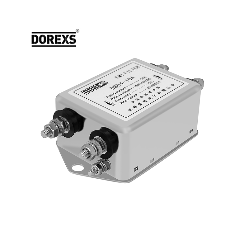
Every factory floor hums with its own electrical fingerprint. A textile plant's variable frequency drives chatter differently than a steel mill's arc furnace, and the noise they inject back into the power line is anything but interchangeable. When engineers grab an off-the-shelf filter based on a catalog spec sheet, they end up suppressing frequencies that aren't even present while letting the real culprits slip through. The result isn't just wasted money—it's nuisance tripping, sensor glitches, and premature wear on sensitive equipment.
The trouble starts with how generic filters are rated. Standard insertion loss curves assume clean 50-ohm source and load impedances, a fantasy in an industrial setting where cables run hundreds of feet and motors cycle unpredictably. A filter that looks perfect on paper can resonate with a particular drive's switching frequency, amplifying noise instead of blocking it. You need to measure the actual conducted emissions spectrum, account for grounding topology, and consider load transients before selecting or designing a filter. Otherwise, you're just guessing with expensive components.
Custom power filters don't have to mean exotic or costly. By analyzing the harmonic profile of your specific machinery—down to the pulse-width modulation scheme and cable capacitance—you can build a targeted network that clamps the worst offenders without over-engineering. Some plants discover they only need a simple common-mode choke plus a carefully chosen X-capacitor, while others require a multi-stage Pi filter with damping resistors. The point is to treat the noise signature as a unique problem, not a checkbox on a procurement form. Your uptime and your budget will thank you.
The Hidden Cost of Skimping on Differential Mode Attenuation
Designers often focus on common mode noise because it's the usual suspect in emissions testing failures. But differential mode attenuation gets quietly overlooked, and that oversight carries a real price. When you skimp on filtering the differential component, you're not just accepting a bit more ripple on the power rail—you're inviting intermittent data corruption, unexplained resets, and field failures that never reproduce on the bench. The cost shows up later, after the product ships, in debugging marathons and customer returns that no amount of firmware patching can fully fix.
There's also a thermal and efficiency angle that rarely makes it into the initial bill of materials. A marginally filtered differential signal forces downstream regulators and transceivers to work harder, burning power to reject noise that should have been handled earlier. Over the lifespan of a device, that inefficiency accumulates into hotter enclosures, shorter component life, and a larger battery or heatsink than the design would otherwise need. What looks like a few cents saved on capacitors or ferrites becomes dollars spent on thermal management and warranty claims.
The hidden cost is ultimately a matter of margin erosion. Every decibel of differential attenuation you skip erodes the signal-to-noise budget that keeps timing margins intact. High-speed interfaces like USB, Ethernet, and DDR memory live or die by those margins. When differential noise eats into them, you see flaky link training, dropped packets, and memory errors that masquerade as software bugs. Teams burn weeks chasing ghosts in code, only to find the root cause was a missing ferrite bead or an undersized common-mode choke. The fix is cheap at the prototype stage, but once the layout is locked and the production line is moving, retrofitting proper differential filtering costs more than the entire filtering budget would have from the start.
Grounding Strategies That Make or Break Filter Performance
It’s easy to assume a filter’s attenuation numbers tell the whole story, but those figures are typically measured with ideal grounding. In a real enclosure, the return path quality often dictates what you actually get. A filter that looks great on a datasheet can fall apart when its ground connection is a long pigtail wire to a distant chassis point, because that wire acts as an inductor at high frequencies and lets noise bypass the intended filtering.
One common trap is treating all ground points as equal. A filter’s ground terminal tied to a noisy digital ground plane will pick up the very interference you’re trying to suppress. Instead, the filter should reference the same quiet chassis ground as the shielded enclosure—ideally at the point where cables enter or leave. Mixing signal and power grounds through the filter can create ground loops that inject hum or ringing into sensitive circuits.
For robust performance, keep the grounding path short, wide, and direct. Use a dedicated ground plane or a low-inductance strap to the chassis, and avoid routing filter grounds through connectors that add impedance. In many designs, a single-point ground at the filter’s mounting location works best, but verify with a network analyzer or a simple noise probe rather than assuming. Small changes in ground layout often shift the filter’s resonance points dramatically, so iteration is part of the process.
When Standard Filters Fail: Custom OEM Solutions That Fit Tight Spaces
Most off-the-shelf filters are designed for generous enclosures, but real equipment rarely offers that luxury. When a pump, compressor, or portable analyzer has only a few centimeters of clearance, the usual catalog part becomes a liability. The flange is too wide, the housing too long, or the inlet orientation points the wrong way. Trying to force a standard unit into these spaces leads to kinked lines, restricted airflow, and mounting brackets that look like an afterthought. Custom OEM filtration starts from the opposite direction: it takes the available envelope as the primary constraint and builds the filter around it.
That shift in approach changes everything about the design. A custom solution might relocate the inlet to the side, reduce the overall length by integrating the end cap with the housing, or use a low-profile pleat pack that preserves media area without adding bulk. One client in the medical device sector needed a 37 mm diameter filter with a 90-degree barbed fitting that could handle 12 L/min of air while fitting behind a display panel. No standard part came close. With an OEM partner, the filter was prototyped within two weeks and produced at scale without disrupting the device's interior layout.
The payoff is not just physical fit. A filter designed for the exact flow rate, particle load, and pressure drop of the application lasts longer and causes fewer service interventions. And because the housing, media, and connections are matched to the machine rather than adapted to it, assembly time drops and the final product looks intentional rather than patched together. When space is the hardest specification to meet, custom OEM filtration turns a design headache into a quiet competitive advantage.
From Anecdote to Evidence: Bench Testing EMI Filters Under Real Loads
Every EMI filter looks perfect on a datasheet, but the moment it meets a real motor drive or a switching converter, those tidy attenuation curves often fall apart. I used to trust vendor specs and the occasional war story from a colleague, only to find the same filter behaving completely differently on my bench. The turning point came when I stopped treating filter selection as tribal knowledge and started running repeatable tests under actual operating conditions.
The setup is straightforward but unforgiving: replace the dummy load with the real thing, whether it's a three-phase inverter, a battery charger, or a stack of DC-DC bricks. Then measure conducted emissions the way the standards do, with a LISN and a spectrum analyzer, while sweeping the load from idle to full throttle. What you see is rarely what the insertion loss graph promised. Differential mode noise can spike under partial load, common mode chokes can saturate when DC current rises, and resonances shift with temperature.
Once you have that data, the anecdotes lose their grip. You know which filter topology holds up at 80% load, which one rings at 200 kHz, and which one needs extra damping just to survive a cold start. That kind of evidence doesn't just settle arguments; it shortens design cycles and keeps field returns from turning into folklore.
FAQ
Underestimating common-mode noise, ignoring impedance mismatches, and selecting only by rated current without checking voltage derating at high temperatures. Another mistake is placing the filter too far from the drive, which can reintroduce noise.
Use the continuous input current of the drive at full load, not the motor nameplate current. Add margin for harmonics and high crest factors. Many engineers derate by 10-15% for ambient temperatures above 40°C.
Insertion loss curves show how much attenuation the filter provides across frequency, but they are measured under 50-ohm conditions. In real systems with low impedance, performance can differ. Look for filters with high attenuation in the 150 kHz to 30 MHz range where most conducted emissions occur.
Three-phase filters are needed for most industrial motor drives and inverters. Single-phase filters suit smaller auxiliary supplies. For three-phase systems with neutral, a four-line filter may be necessary to handle both common-mode and differential-mode currents.
Common references include EN 55011 / CISPR 11 for conducted emissions, IEC 61800-3 for adjustable speed drives, and UL 1283 for electromagnetic interference filters. Always check the end equipment's intended market for regional compliance.
AC filters have Y capacitors that create leakage current to ground. For industrial systems, excessive leakage can trip residual current devices or cause safety issues. Choose filters with lower capacitance if the system has sensitive grounding, and verify against IEC 60950-1 or IEC 62368-1 limits.
Single-stage filters are compact and cost-effective for moderate noise. Two-stage filters provide higher attenuation for severe EMI or when the drive uses high switching frequencies. If you're near the emissions limit, a two-stage design gives extra headroom without much larger footprint.
Conclusion
Selecting an OEM AC EMI filter for industrial power systems demands more than comparing datasheet numbers. The first step is reading between the lines: insertion loss curves measured at 50 ohms rarely reflect real-world impedance mismatches, and attenuation figures without current derating under load tell only half the story. Industrial noise is not a single signature—motor drives, inverters, and switching power supplies each produce distinct common-mode and differential-mode profiles. A filter optimized for one environment may underperform in another, so treating all applications as identical leads to field failures. Equally critical is differential-mode attenuation, which is often skimped on to save cost or space. Yet weak differential-mode filtering allows high-frequency ripple to circulate through the power stage, degrading capacitors and even causing controller resets. The long-term reliability hit far outweighs the upfront savings.
Grounding strategy is where many installations quietly fail. A filter's performance depends on a low-impedance bond to the chassis, and paint, anodizing, or long ground leads can erase 20 dB of expected attenuation. Standard off-the-shelf filters rarely fit the mechanical reality of compact industrial equipment, so custom OEM solutions—shaped housings, integrated bus bars, or combined connector-filter modules—become necessary not as luxuries but as functional requirements. Finally, bench testing under real loads closes the gap between anecdote and evidence. Temperature rise at full current, saturation behavior with DC offset, and noise measurements with actual motor loads reveal weaknesses no datasheet can show. A disciplined selection process that pairs electrical characterization with mechanical and thermal validation produces a filter that survives not just the first test, but years of hard industrial use.
Contact Us
Contact Person: Eric
Email: [email protected]
Tel/WhatsApp: 8618117837140
Website: https://www.emcdorexs.com