
Cylinder Head Assembly Maker: Mastering Precision Engine Building Techniques
2026-07-25
Precision in cylinder head assembly isn't just a skill—it's the heartbeat of high-performance engines. Whether you're chasing podium finishes or perfecting a restoration, every micron matters. At DDR, we believe that mastering these techniques separates the builders from the dreamers. This guide strips away the noise, delivering hard-won insights that turn complex procedures into repeatable triumphs.
Cylinder Head Blueprinting: Achieving Flawless Deck Surfaces and Guide Alignment
Blueprinting a cylinder head goes far beyond a casual resurface. It starts with a meticulous evaluation of the deck surface for flatness. Even a few thousandths of an inch of warpage can compromise head gasket sealing under high cylinder pressures. The correction process often involves a light skim cut, but the real craft lies in preserving the correct surface finish—too smooth and the gasket can't bite; too rough and you invite premature failure. The goal is a dead-flat plane that mates perfectly with the block, achieved through careful setup on a rigid mill and multiple passes with a CBN or PCD cutter, followed by a tactile check with a precision straightedge and feeler gauges.
Valve guide alignment is another pillar of a blueprint-quality head. Guides that are worn, bell-mouthed, or not concentrically aligned with the valve seats cause the valve to wobble at high lift, killing airflow and seat longevity. Replacing guides demands more than just pressing in new ones—it requires honing to exact clearances and verifying concentricity with a dial indicator. In performance builds, guide-to-seat runout is held to under 0.001 inch, often checked with a pilot and a precision bore gauge. This attention ensures the valve stem glides with minimal friction while maintaining a tight seal at the seat, even at elevated rpm.
The intersection of deck flatness and guide precision defines the head's ultimate capability. A warped deck can distort the seat and guide alignment under torque, negating the machine work done on the bench. That's why experienced builders often stress-plate torque the head during final checks, simulating installed conditions. Only when the surface is dead true and every guide is perfectly positioned can the head deliver its full potential—consistent compression, crisp throttle response, and durability that outlasts standard rebuilds.
Selecting and Prepping Castings: The Hidden Role of Grain Structure and Heat Cycling
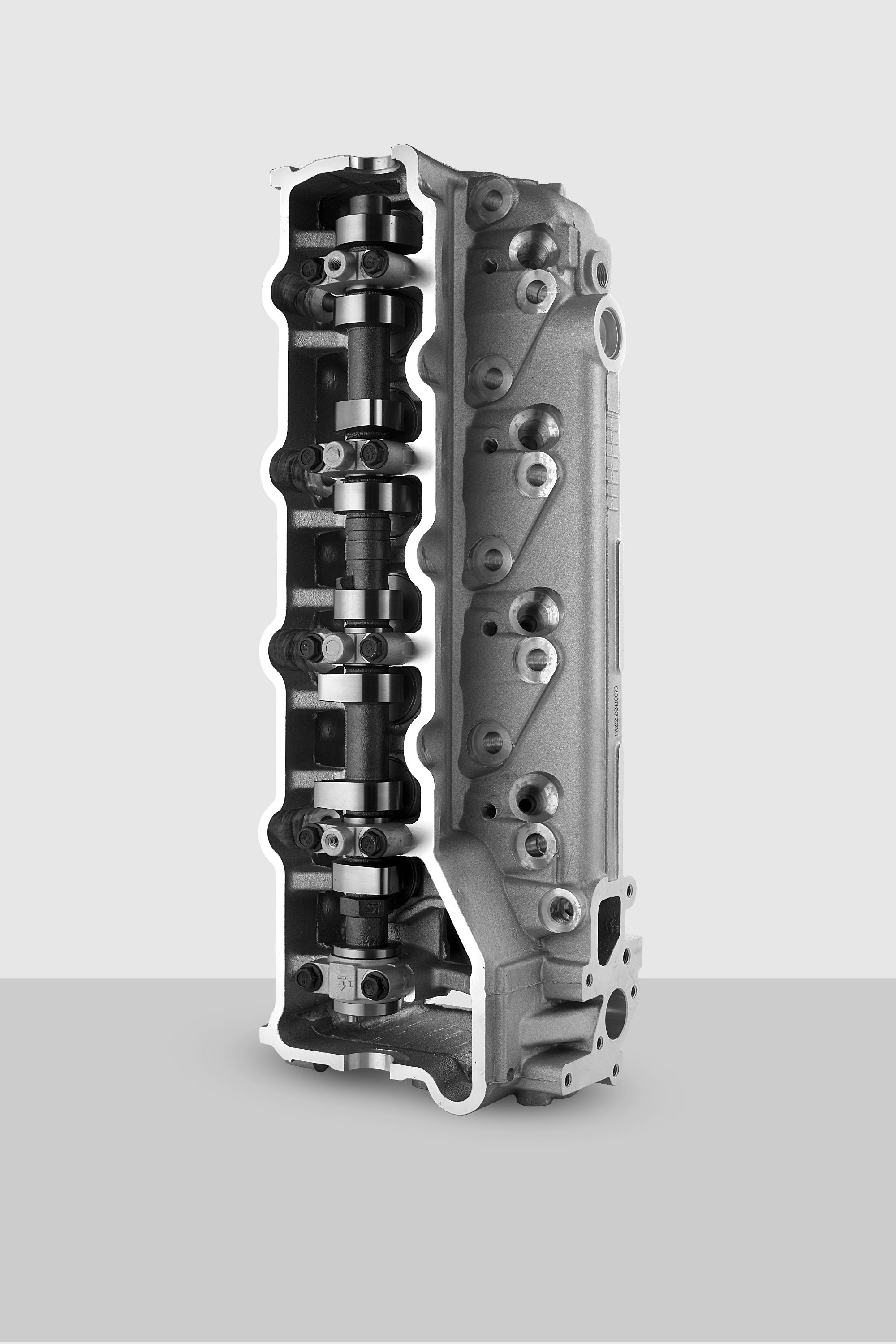
Choosing a raw casting involves more than checking dimensions and surface finish. The grain structure locked inside the metal tells a story of how the part was poured, cooled, and handled before it ever reached your hands. A coarse, uneven grain often hides residual stresses that will warp a workpiece the moment you break the surface. Look beyond the obvious—study the casting’s history if you can, and learn to read the subtle marks left by the mold and cooling process.
Heat cycling before any serious machining can be the difference between a stable, accurate part and a creeping nightmare. Repeated, controlled thermal excursions relieve internal tensions without shocking the material. A slow climb to a moderate temperature, held long enough for the core to equalize, lets the metal reorganize at the grain level. Done right, the casting emerges more predictable, less likely to twist after roughing, and ready to hold tight tolerances.
Prep work also means knowing when to leave extra stock. Aggressive cleanup can tear into a skin that’s structurally different from the interior, inviting distortion. Instead, plan your cuts to gradually peel away layers, preserving the refined grain near the surface until the final stages. The real craft lies in respecting how the metal’s internal character responds to every thermal and mechanical touch.
Airflow Craft: Developing Port Shapes Unique to Your Engine's Personality
Every engine breathes through its ports, and the shape you carve into those passages determines how air and fuel tumble, swirl, or charge into the cylinder. Think of it not as a simple hole but as a signature piece—like a custom grind on a camshaft, the port’s cross‑section, taper, and surface finish reflect the builder’s intent. When you sit down with a die grinder and a burr, you’re not just chasing a flow number on a bench; you’re shaping the power delivery to match the character you want under the hood. A sharp, straight shot might favor top‑end rush, while a gentle dogleg with a textured wall can fatten the midrange and sharpen throttle response. The trick is to listen to the engine’s character—its rpm band, its intended use, even its exhaust note—and let the metal tell you where it needs to go.
The art lies in the details most people never see. A subtle roof raise just past the valve guide boss can wake up a lazy port without destroying velocity. A carefully rolled short‑turn radius keeps the air attached when the curtain area goes critical. What truly separates a crafted port from a catalog cut is the feel for the boundary layer—knowing when to leave a slight texture to keep fuel in suspension versus polishing to a mirror for a dry‑flow intake. You begin to treat the port walls like contour lines on a map, reading the carbon traces and wet‑flow patterns to decide where to pluck away material and where to let it be. It’s slow, dusty work, but the reward is an engine that pulls with its own distinct voice, a personality that can’t be ordered from a shelf.
Developing a port shape unique to your engine is a conversation between your hands and the cast iron or aluminum. You might start with a basic dye‑chem layout, tracing valve‑to‑bore alignment and pushrod pinch points, but soon you’re chasing a hunch—removing a ridge here, laying back a wall there, blending the bowl until it flows like a stream and not a storm. The real judgment comes when you stop measuring and start feeling: how the burr chatters through an irregular spot, how the airflow hisses on the bench at a certain lift, how the engine leans into the load on a dyno pull. You’re not trying to mimic a textbook curve; you’re building a breathing rhythm that suits your cam events, your compression, your whole combination. When it’s right, you’ll know—because the engine will sing its own song, one that no one else’s can duplicate.
Valve Seat Geometry and Why Concentricity Defines Longevity
When an engine builder talks about valve seats, they're not just discussing a replaceable ring pressed into the head. The geometry of that seemingly simple component dictates how heat transfers, how forcefully the valve closes, and ultimately how many hours an engine can run before performance drops. A precisely cut seat with a multi-angle profile doesn't just seal—it manages the chaotic dance of thermal expansion and contraction that occurs with every combustion cycle. The width of the seating surface, the sharpness of the transition angles, and the blend into the port throat all play a quiet but critical role in how efficiently the valve sheds heat into the cylinder head.
Concentricity is where longevity is truly forged. When the seat insert's center is not perfectly aligned with the valve guide, the valve head doesn't land flat. Instead, it crashes unevenly, creating localized hotspots and micro-welding that erode the sealing surface over time. This misalignment, often invisible to the naked eye, forces the valve to flex slightly with each closure, gradually fatiguing the stem and accelerating guide wear. Shops that skip concentricity verification after guide replacement or seat cutting are essentially building in a countdown clock—one that ticks faster under high RPM or sustained load.
There's an old machinist's saying: the valve head doesn't know if the seat is concentric, but the seat knows if the guide is crooked. True longevity comes from treating the valve, guide, and seat as a single system. When that system is dialed in—when concentricity is held to a couple of tenths, and the seat angles direct flow without sacrificing heat transfer area—the result isn't just a tight seal. It's an engine that maintains compression, resists recession, and runs consistently for seasons without needing a valve job. That's not luck; it's geometry doing its work in silence.
Fastener Science: Stretch Guages, Torque Angles, and the Death of Guesswork
For decades, bolted joint assembly relied heavily on feel, friction estimates, and simple torque wrenches that often led to inconsistent clamp loads. The real turning point came when engineers started looking beyond just torque—realizing that fastener stretch and rotation provide a far more accurate picture of joint integrity. Stretch gauges, which physically measure the elongation of a bolt, eliminate the guesswork caused by thread friction and surface finish variables, offering a direct window into the actual preload achieved.
Torque angle methods further refined the process by combining initial torque with a specified angle of rotation, ensuring the fastener moves past its elastic range into a controlled plastic zone where clamping force becomes highly repeatable. This approach doesn’t just tighten a bolt; it engineers a joint that behaves predictably under cyclic loads and thermal stress. Modern assembly lines integrate these measurements in real time, with data loggers tracing every fastener’s signature curve—a practice that has virtually killed the old culture of guess-and-check.
The shift away from blind torque specifications toward measurement-driven tightening isn’t just about precision; it’s about safety and material optimization. When you can verify stretch or angle precisely, you can design joints with smaller, lighter fasteners without sacrificing reliability. Industries from aerospace to automotive have embraced these techniques, turning fastener science into a disciplined, data-backed field where catastrophic joint failure is increasingly rare—and the old-school smile of a mechanic satisfied by a click sound becomes a relic of the past.
Cold Leak Detection and Wet Flow Bench Insights Before Dyno Day
Before you even strap the engine to the dyno, spending time chasing cold leaks and verifying wet flow patterns can save you a mountain of headaches later. A cold leak test – pressurizing the intake tract or cooling system with regulated air – reveals tiny gaps that would only open under boost or thermal expansion. It's not enough to glance at a boost leak checker and call it good; you need to listen for subtle hisses near injector seats, hose clamps, and gasket flanges, and then confirm with soapy water or leak detection spray. This upfront diligence prevents the classic dyno-day scramble where fueling goes haywire because unmetered air is sneaking in after the mass airflow sensor.
Wet flow bench insights are equally critical, especially if you’ve changed port geometry or injector placement. Watching a calibrated flow stream across the valve and into the combustion chamber under partial lift conditions tells you more than a dry flow number ever will. Pay attention to fuel wash patterns on the back of the intake valve – if there’s pooling or a weird rooster tail at low and mid-lift, you’ll fight fuel distribution issues that won’t show up on an air meter. Even with modern CFD, the visual feedback from a wet bench often exposes swirl inconsistencies or localized rich spots that affect combustion efficiency. Tuning around those physical quirks on the dyno is a losing battle.
When you finally fire up on the dyno, these pre-checks give you a known baseline. Instead of guessing whether a lean spike at 4500 rpm is a tune problem or a mechanical leak, you'll already have confidence in the induction path integrity. The payoff is a shorter, safer tuning session because you’re not chasing ghosts, and you can push for power without risking a meltdown from a surprise lean-out. It’s the difference between a frantic day of troubleshooting and a methodical pull that makes real gains.
FAQ
A cylinder head assembly maker specializes in building and refurbishing the top section of an engine, where the combustion happens. This involves precision fitting of valves, springs, seals, and sometimes camshafts, all while ensuring everything is torqued and aligned to factory or performance specs.
Even a tiny misalignment or improper torque can lead to compression loss, overheating, or catastrophic engine failure. The mating surfaces need to be flat within thousandths of an inch, and component clearances are often measured in microns.
Skipping the cleaning of bolt threads, uneven torquing sequences, reusing non-reusable fasteners, and not checking valve spring installed height are all classic errors. Overlooking these can cause uneven clamping force and premature wear.
You'll need a good torque wrench, a valve spring compressor, a straightedge and feeler gauges for checking flatness, a micrometer for valve stems, and a dial indicator for measuring runout. A dedicated valve lapping tool and a leak-down tester can also save you a lot of trouble later.
Surface preparation is everything. Both the block deck and the head must be spotlessly clean and checked for flatness. Follow the manufacturer's torque sequence and incremental torque steps, and use the exact gasket type recommended for your build—MLS, composite, or copper all have different requirements.
After confirming the guide bore is clean and within spec, the guide is often chilled and the head heated for an interference fit. Once seated, it's reamed to size. Seals then get lubricated and carefully pushed onto the guide without nicking the sealing lip, using a bullet tool if needed to protect them from sharp edges.
It depends. CNC heads often have near-perfect concentricity, but many builders still do a light lap just to verify the contact pattern. If you're reusing old valves or seats, lapping can clean up minor imperfections, but it's no substitute for a proper machine shop valve job if the seats are worn.
It's not about hogging out material everywhere. The focus is on the bowl area and the valve seat transition, blending the short-side radius smoothly. Experienced builders use flow bench data to avoid ruining velocity while maximizing CFM, and they know that a glassy mirror finish isn't always best—a slight texture can aid fuel atomization.
Conclusion
In the world of high-performance engine building, the cylinder head is where power lives or dies. A true cylinder head assembly maker doesn't just bolt parts together—they approach the work like a machinist-artist, starting with absolute precision at the deck surface. Blueprinting reveals unevenness that factory tolerances overlook, and correcting guide alignment through careful honing ensures that valves don’t side-load and wear out prematurely. Beneath the surface, the casting itself matters immensely: grain structure and heat cycling history dictate how the head will behave under stress. Seasoned builders know that freshly cast aluminum can wander dimensionally, so they stabilize the material before ever cutting a seat pocket. This foundation lets them carve ports with personality, not just copy a template. Airflow development becomes a conversation between the engine’s intended character—broad torque or screaming top-end—and the subtle shaping of the short-turn radius, throat, and bowl blend. Every curve is deliberate.
That obsession with precision flows into the valve job, where seat concentricity defines longevity more than any exotic material. Runout beyond half a thousandth invites leaks, hot spots, and eventual recession. The smart builder uses modern fastener science to lock it all together, trading torque wrenches for stretch gauges and torque-angle methods that eliminate guesswork from clamp load. Even the best assembly can hide flaws, so cold leak detection with low-pressure air and wet flow bench testing reveal how fuel and air actually behave before the engine ever fires. These tools turn the cylinder head into a known quantity, not a source of dyno-day anxiety. In the end, mastering cylinder head assembly means respecting every layer—metallurgy, geometry, fluid dynamics, and clamping force—as part of a unified system. The reward is an engine that breathes with intent, runs reliably, and delivers exactly the power it was built to make.
Contact Us
Contact Person: Shelly
Email: [email protected]
Tel/WhatsApp: 8613967667688
Website: https://www.yongyu.com/