
Custom USB 3.2 Gen 2 Type-C Cable Options for Any Project
2026-11-02
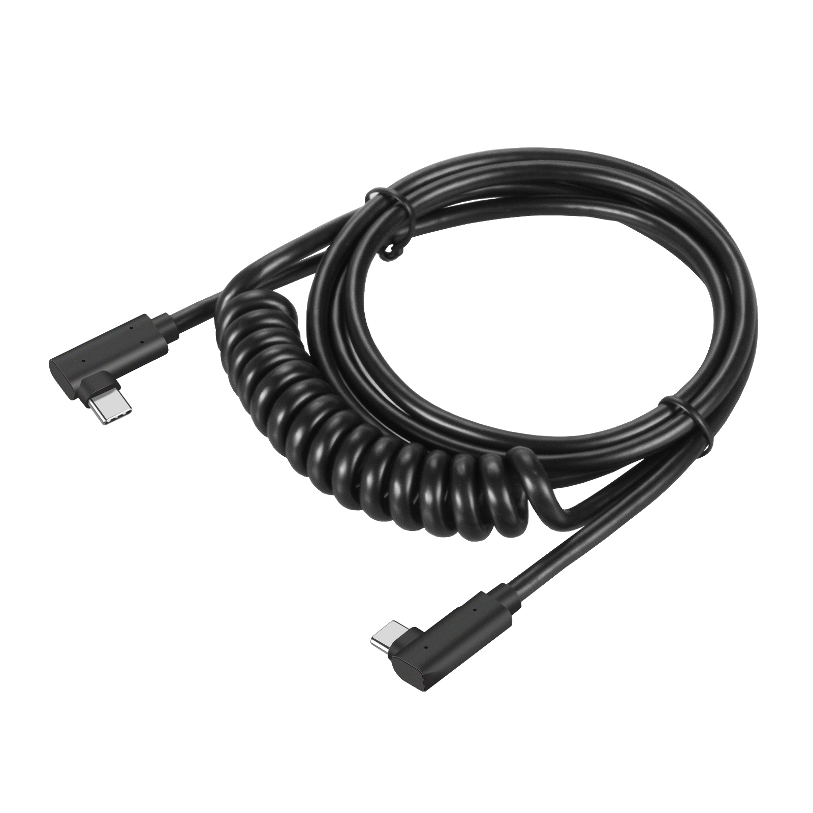
Every project has its own set of demands, but off-the-shelf USB cables rarely keep up. When you need custom USB 3.2 Gen 2 Type-C solutions—whether for high-speed data, power delivery, or unique connector angles—EBCYX gives you the flexibility to specify exactly what you need, down to the last detail. No more settling for nearly right. Here's how to build the perfect cable for your next build.
Why Stock USB-C Cables Can't Handle Your Custom Enclosure
Most off-the-shelf USB-C cables are built around the assumption that the connector will sit flush against a flat, open port. The molded plastic overmold behind the plug typically flares out to a width of 9–10 mm and extends several millimeters past the connector face. If your custom enclosure has a recessed port, a curved cutout, or any kind of lip that sits closer than about 5 mm to the mating surface, that stock overmold hits the wall long before the USB-C plug reaches the receptacle. You end up with a cable that either can't be fully inserted or has to be forced at an angle, which puts stress on both the connector and the PCB.
Another issue is strain relief. Stock cables use a thick, stiff boot that's designed to flex only in one direction and usually assumes the cable will exit straight back. Custom enclosures often need the cable to make an immediate 90-degree bend or route through a narrow channel. A standard boot won't accommodate that without kinking the cable or levering the connector out of its socket. When you combine that with the fact that many stock cables have minimal shielding and no grounding tab, you get intermittent disconnects and EMI problems that only show up after the product is assembled.
The physical dimensions are only half the story. Even if you manage to modify the opening, stock cable assemblies rarely match the wire gauge or signal integrity requirements of a custom device. USB-C expects specific impedance control and conductor lengths, and an off-the-shelf cable might use thinner copper or skip the required shielding layers to save cost. In a custom enclosure where the cable is routed past switching regulators or next to a display driver, that compromise turns into data errors or failed negotiation with fast chargers. A custom cable with a low-profile overmold and tailored shielding is the only reliable fix.
Pinouts and Wiring Options That Match Your Board's Needs
Most dev boards lock you into a fixed pin map, but here the breakout headers expose nearly every GPIO with a deliberate layout. You can route I2C, SPI, UART, PWM, and analog inputs without fighting over shared lines. A few pins have dual functions, so the silkscreen marks the secondary roles instead of leaving you to guess.
Power and ground pairs are scattered at sensible points, not just dumped in one corner. This makes it easier to keep return paths short when you're wiring sensors or level shifters across the board. If you need more current, there are two headers that can take an external 5V rail directly, bypassing the onboard regulator without cutting traces.
The default wiring option favors breadboard use, but the same signals appear on a compact edge connector. That means you can prototype with jumper wires and then move to a flat-flex cable for a tighter enclosure without changing firmware or re-mapping pins.
Choosing Outer Jacket Materials for Flex, Heat, or Chemical Resistance
When an application demands constant bending or twisting, a stiff jacket will crack long before the conductor fails. Look for elastomeric options like polyurethane or specialized PVC blends that retain pliability even after thousands of flex cycles. A simple field test: bend a sample repeatedly by hand and watch for whitening or surface fissures—those are early warnings of jacket fatigue.
For high-temperature environments, fluoropolymers such as FEP or PFA offer excellent heat resistance but may sacrifice flexibility. Silicone jackets bridge that gap, handling continuous exposure up to 200°C while staying supple enough for tight routing. Always verify the temperature rating against actual operating conditions, not just brief peaks, because thermal aging degrades most polymers faster than mechanical stress alone.
Chemical resistance requires matching the jacket polymer to the specific solvents, oils, or cleaning agents present. Polyethylene and cross-linked polyolefins resist many acids and alkalis, while polyurethane excels against fuels and hydraulic fluids but swells in strong polar solvents. Request immersion test data from the manufacturer rather than relying on generic compatibility charts—real-world chemical cocktails often behave differently than single-substance lab results.
Balancing USB 3.2 Gen 2 Speeds with USB Power Delivery
The real headache with USB 3.2 Gen 2 and Power Delivery isn't the spec sheet—it's what happens when both try to run at full tilt. On paper, the Type-C connector can carry 10Gbps data and up to 100W (or 240W with EPR) at the same time, but in practice, the controller inside your laptop or dock has to juggle power negotiation, signal retiming, and thermal headroom all at once. Push too much current through a thin cable while also pumping 10Gbps and you'll see dropouts, reduced charging speeds, or both.
Cable choice quietly makes or breaks this balance. A cable labeled "USB 3.2 Gen 2" might handle the data rate but lack an e-marker chip for reliable PD handshakes. Conversely, a 100W PD cable could be wired for USB 2.0 data only. For a hub or dock that promises both, look for active electronics—retimers and redrivers—that clean up the signal after it's been split off from the power path. Otherwise, you'll end up with a device that charges fast but stutters on large file transfers.
Heat is another silent limiter. Running 10Gbps encoding plus 60W+ power delivery through one port builds up thermal load at the connector and the dock's internal bridge. Manufacturers often throttle one side to keep the other stable. That's why some docks reduce charging wattage during heavy data loads, or cap transfer speeds when the laptop battery is nearly full. Knowing this helps you set realistic expectations: you can have speed and power, but rarely both at their absolute maximum for sustained periods.
Connector Orientation and Locking Features Worth Considering
Most engineers focus on pin count and current rating, but connector orientation quietly dictates how much space a design actually needs. A right-angle connector can save vertical clearance, but it also forces the cable to exit sideways, which might crowd adjacent components. Vertical connectors, on the other hand, keep the cable path straight but add height that a slim enclosure may not tolerate. You have to think about where the mating force will go too — if you push a vertical connector from the top, the PCB absorbs that load, whereas a right-angle design may put shear stress on solder joints unless there's additional mechanical support.
Locking features often get treated as an afterthought until a field failure happens. A simple friction lock might be enough for a stationary device, but anything that vibrates or gets handled regularly needs positive retention. Latch-style locks are popular because they give an audible click and quick release, but they can be fragile if the plastic tab is exposed. Threaded collars are rugged but slow to mate, and push-pull mechanisms offer a nice balance if you're willing to pay for the extra machining. The key is to match the locking style to the actual abuse the connection will see, not just the cheapest option on the datasheet.
Another angle worth considering is how orientation interacts with locking. Some connectors are only rated for a specific mating direction under load — a right-angle connector with a locking latch may not perform the same if the cable is pulled sideways versus inline. If you're routing cables in a tight chassis, you might need a connector that locks but still allows a small amount of float to prevent stress on the termination. Don't assume that a good locking mechanism compensates for a bad orientation choice; they need to work together.
Scaling from Prototype to Production Without Redesign Headaches
Most teams discover the hard way that a prototype built for demo speed rarely survives contact with real users. The code that looked clever at a hackathon becomes a liability when every request spawns a new connection pool or when hard-coded credentials are scattered across three different services. Instead of treating the prototype as a throwaway, use it to surface the risky assumptions early: measure where latency actually comes from, log every integration point, and resist the urge to paper over data inconsistencies with one-off fixes.
The most reliable guard against a costly redesign is to keep the seams between components boringly predictable. Define the data contracts before adding new features, keep background jobs idempotent, and make configuration changes deployable without a full rebuild. When a piece of the prototype starts wobbling under load, isolate it behind an interface rather than rewriting the surrounding logic. This way, scaling becomes a series of small swaps instead of a big-bang migration.
Finally, practice scaling the parts nobody thinks about until it is too late. Run the queue workers with more than one instance, throttle outbound calls to third-party APIs, and test the database migrations against a copy of real data. Teams that avoid redesign headaches are not the ones with perfect foresight; they are the ones who left enough slack in the architecture to adjust the path without tearing up the road.
FAQ
We let you dictate nearly every aspect of the build—conductor gauge, insulation type, jacket compound, connector orientation, and even the overmold color. That means the cable fits the project instead of forcing the project to fit a stock cable.
Yes, that's actually one of the most common requests. You can specify a straight plug on one end and a right-angle or even a vertical plug on the other, which really helps with tight enclosures and clean routing.
For runs beyond a couple of meters, we switch to thicker 28 or 26 AWG conductors and add active retimer chips inside the connector shells. That keeps bit errors low without needing a repeater in the middle.
All versions include an E-marker chip, so you're good for up to 100 watts at 20 volts and 5 amps. If your project needs only 60 watts, we can still use the same chip but with lighter conductors to save weight.
Absolutely. The overmold can be molded in a Pantone-matched color, and we can also laser-etch or pad-print a logo or part number on the connector housing. There's no setup charge for the first iteration.
We keep the floor at 100 units for fully custom assemblies, which is usually enough to validate a design without committing to huge inventory. For small pilot runs, we can often do 25 pieces with a modest surcharge.
Yes, we offer a double-shielded option with aluminum foil plus a high-coverage tinned copper braid. Combined with 360-degree termination to the connector shell, it stands up well to motor drives, welding equipment, and other noisy environments.
Conclusion
Off-the-shelf USB-C cables rarely survive the jump from bench testing to a real enclosure. Their molded strain reliefs rarely fit tight cutouts, internal wiring choices are locked down, and the default jacket material usually ignores flex cycles or chemical exposure. When you control the pinout and wiring configuration, though, the cable stops being a generic accessory and becomes part of the board-to-board interface. You can drop unused high-speed pairs, reroute sideband signals, or specify shielded twisted pairs where signal integrity matters most. Outer jacket selection follows the same logic: polyurethane handles constant bending, silicone copes with heat, and FEP or TPE variants resist oils, solvents, and abrasion. These choices prevent failures that look like connector issues but actually trace back to insulation cracking or conductor fatigue.
Speed and power delivery no longer have to trade against each other. A properly built custom cable can carry 10 Gbps USB 3.2 Gen 2 data while negotiating up to 100 W, provided the wire gauge, shielding, and e-marker chip are matched to the application. Connector orientation is another overlooked variable; right-angle, left-angle, or vertical plugs can reduce internal stress, while screw-lock or latch-style housings keep the connection secure in vibration-prone equipment. Prototype builds often hide these integration details until the first full assembly, which is why moving to production without a cable partner invites late redesigns. Starting with a configurable assembly and locking the exact length, jacket, pinout, and locking style early keeps the path from pilot run to volume build much shorter. The result is a cable that fits the mechanical design, survives the operating environment, and carries both data and power exactly as the project demands.
Contact Us
Contact Person: David Yang
Email: [email protected]
Tel/WhatsApp: 8615814734054
Website: https://www.ebcyx.com/